Endmill Setup
G-Code Editor
No file loadedFile Listing
| Filename | Size | Actions |
|---|---|---|
|
Not Connected
Please connect to load files...
|
||
Tools
Various tools and widgets — new tools added over time.
| Tool | Z-Offset | Dia |
|---|---|---|
| No tools loaded. | ||
Geometry (G10 L1)
Description
For manual tool change, use the TLO buttons in the MTC modal (Set Ref + Measure) instead of managing Z offsets here. This tool table is primarily for ATC workflows.
Flatten a spoilboard or stock material. For best results use a surfacing router bit and ensure your router head is trammed perpendicular to the bed.
Surfacing Dimensions
Starts at the front-left of the entered area and surfaces the width and length.
Starts at the front-left of the entered area and surfaces the width and length.
Surfacing Depth Control
Total amount removed below the current Z zero.
Maximum Z depth removed on each pass.
Tools & Feeds
Percentage of the tool diameter overlapped on each pass.
Spindle speed command added to the generated job (For Variable Speed spindles).
Options
Chooses whether the main surfacing passes run along X or Y.
Adds M8 at the start of the job and turns coolant off at the end.
Adds a cleanup pass around the outside edge of the surfacing area.
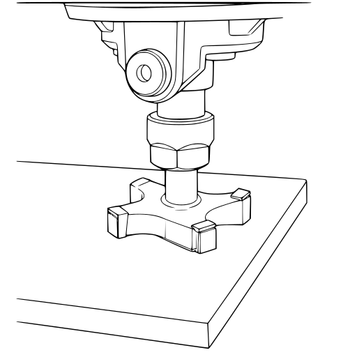
- Install the Router Bit.
- Jog the machine so the centre of the router bit is over the front left corner of the stock material.
- Zero X and Y.
- Zero Z to the highest point of the stock material.
- Turn on your Router Head & Dust Extractor (If applicable).
- Press Run Job.
- Install the Router Bit.
- Home the machine.
- Zero Z to the highest point of the spoilboard.
- Turn on your Router Head & Dust Extractor (If applicable).
- Press Run Job.
Engrave a grid pattern of lines starting at front-left of machine with optional ruler marks and numbers. For best results, use a V-bit.
Grid Dimensions
Grid Depth Control
Tools & Feeds
Spindle speed command added to the generated job (For Variable Speed spindles).
Options
Include markings and numbers.
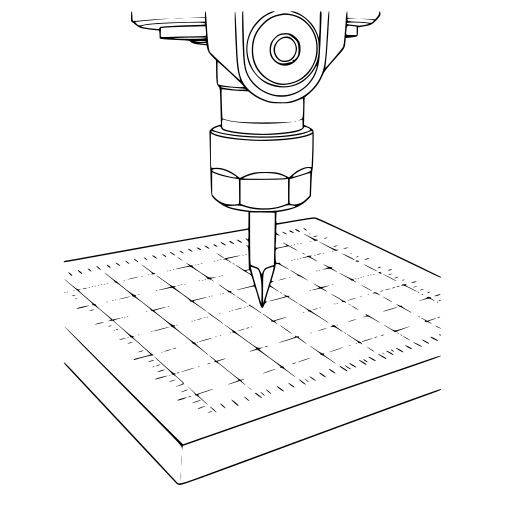
- Install a V-bit.
- Home the machine.
- Zero Z to the highest point of the spoilboard.
- Turn on your Router Head & Dust Extractor (If applicable).
- Press Run Job.
Cut a recessed bowl or tray with rounded inside corners. For best results use a ball nose bit.
Bowl Dimensions
Radius used to round the inside corners of the bowl.
Bowl Depth Control
Total amount removed below the current Z zero.
Maximum Z depth removed on each pass.
Tools & Feeds
Percentage of the tool diameter overlapped on each pass.
Spindle speed command added to the generated job (For Variable Speed spindles).
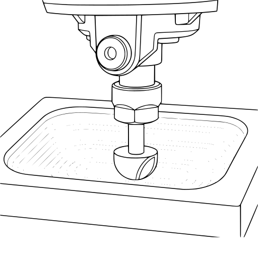
- Install a ball nose bit.
- Zero X and Y at the centre of the intended bowl position.
- Zero Z to the highest point of the stock material.
- Press Run Job.
Probing
Tool offsets, edge finding, and alignment.
Plate Configuration
The X distance from the plate contact surface to the workpiece surface.
The Y distance from the plate contact surface to the workpiece surface.
The Z distance from the plate contact surface to the workpiece surface.
How far the outside corner routine moves in X and Y from the Start Here hole toward the plate centre before probing Z.
Movement
The main probing speed used for the first approach move.
The maximum distance the tool is allowed to travel while searching for a probe contact.
How far the tool backs off immediately after a probe touch before continuing.
Extra X/Y spacing used when moving around the probe plate or feature so the tool stays clear before the next move.
The starting Z depth used when positioning for outside corner routines.
Use a fixed tool setter to establish a Z reference with your first tool, then measure subsequent tools. The offset is applied to the active Work Coordinate System.
Enter the fixed tool setter location in machine coordinates. Establish a reference with the first tool, then measure each subsequent tool to update Z automatically.
Probe an outside corner to set X, Y, and Z zero.
Enter the diameter of the endmill or dowel pin currently in the collet. This is used to calculate the tool radius when setting the correct X/Y zero from the probe contact point.
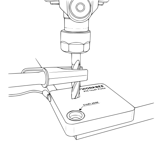
Place probe plate on the front left outside corner. Position the tool above the Start Here hole before probing.
Probe a single surface to set its X/Y/Z zero.
Enter the diameter of the endmill or dowel pin currently in the collet. This is used to calculate the tool radius when setting the correct X/Y zero from the probe contact point.
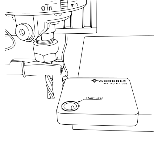
Place probe plate on the left surface. Position the tool beside the plate so it can probe toward it.
Position the probe tip approximately above the center of the feature you are probing. Approx Size is how far out the probe will travel before looking for edges. Inside Pockets start from center and move outward. Outer Features (Rect/Circular) move beyond the measurements then probe toward the center.
Feature / Stock Dimensions
Approximate size of the feature. Extra clearance is added automatically.
Inside Pocket
Find the center of a pocket or hole. Starts at center, probes outward.
Rect Feature
Find the center of a rectangular stock or feature. Probes from outside in.
Circular Feature
Find the center of a round stock or feature.
Inside Corner
Probe two edges of an inside corner to set work zero.
Workpiece Rotation
Probes two points along an edge to determine the angle of the material. Use this to physically align your stock.
Distance to move along X before probing P2.
Measured Angle
0.00°Ready to probe.
Limits
Control & Probe
Motor Status
Pin Configuration & State
Power Supply
Spindles
Select active spindle and control speed.
RGB LED
Test RGB LED strips connected to the controller. Pick a color or use the picker below.
Waiting for firmware info...